

Metal Film Precision Resistor (CSR Series)
Metal Film Precision Resistor (CSR Series)
category:
MELF RESISTOR
Model :
VIKING42
- Product description
- Product parameters
- Product parameters
-
- Commodity name: Metal Film Precision Resistor (CSR Series)
- Commodity ID: VIKING42
MetalfilmprecisionMELFresistor.Thinfilmwithexcellentstabilit,SnterminationonNibarrier,tighttoleranceandlowTCR,precisionMELFresistor,SMDenabledstructure.RecommendLandPatternFeatures· Excellentoverallst
Metal film precision MELF resistor. Thin film with excellent stabilit , Sn termination on Ni barrier, tight tolerance and low TCR , precision MELF resistor, SMD enabled structure.
 Features
· Excellent overall stability.
· Tight tolerance down to ±0.1%.
· Extremely low TCR down to ±10 PPM/°C.
· High power rating up to 1 Watts.Applications
· Telecommunication
· Medical Equipment
· Measurement/Testing EquipmentConstruction
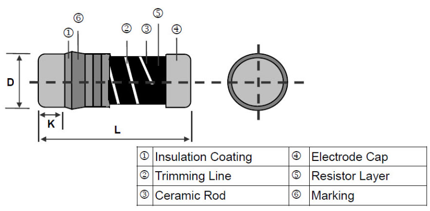
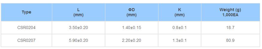
Dimensions (Unit: mm)
Part Numbering

Recommend Land Pattern

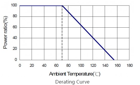
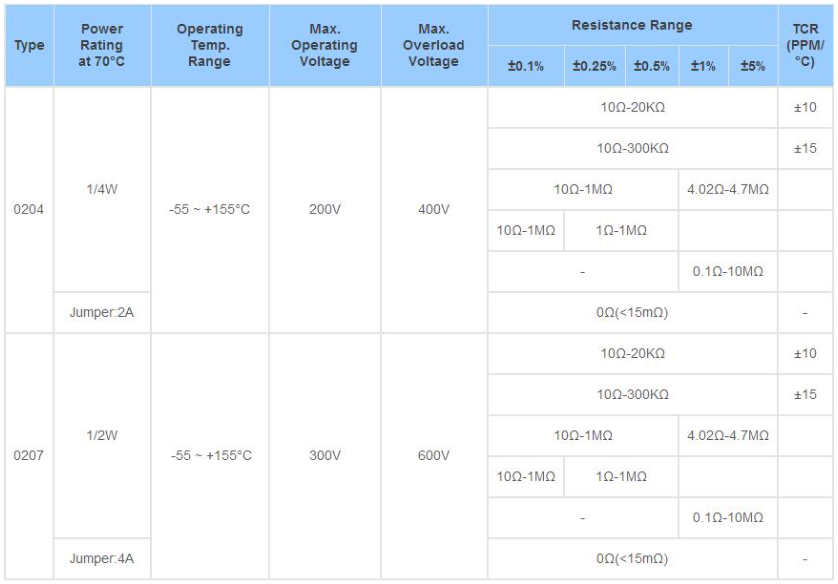
Standard Electrical Specifications
Pulse Withstanding Capacity
The single impulse graph is the result of 50 impulses of rectangular shape applied at one-minute intervals.
The limit of acceptance was a shift in resistance of less than 1% from the initial value. The power applied was subject to the restrictions of the maximum permissible impulse voltage graph shown.
Continuous Pulse
The continuous load graph was obtained by applying repetitive rectangular pulses where the pulse period
was adjusted so that the average power dissipated in the resistor was equal to its rated power at 70°C. Again the limit of acceptance was a shift in resistance of less than 1% from the initial value.
Frequency behavior
Resistors are designed to function according to ohmic laws. This is basically true of resistors for frequencies up to 100kHz. At higher frequencies, there is an additional contribution to the impedance by an ideal resistor switched in series with a coil and both switched parallel to a capacitor. The values of the capacitance and inductance are mainly determined by the dimensions of the terminations and the conductive path length.
The environment surrounding components has a large influence on the behavior of the component on the printed-circuit board.Lightning Surge
Resistors are tested in accordance with IEC 60 115-1 using both 1.2/50us and 10/700us pulse shapes. The limit of acceptance is a shift in resistance of less than 0.5% from the initial value.
产品详情
Metal film precision MELF resistor. Thin film with excellent stabilit , Sn termination on Ni barrier, tight tolerance and low TCR , precision MELF resistor, SMD enabled structure.
Features
· Excellent overall stability.
· Tight tolerance down to ±0.1%.
· Extremely low TCR down to ±10 PPM/°C.
· High power rating up to 1 Watts.
Applications
· Telecommunication
· Medical Equipment
· Measurement/Testing Equipment
Construction
Dimensions (Unit: mm)
Part Numbering
Recommend Land Pattern
Standard Electrical Specifications
Pulse Withstanding Capacity
The single impulse graph is the result of 50 impulses of rectangular shape applied at one-minute intervals.
The limit of acceptance was a shift in resistance of less than 1% from the initial value. The power applied was subject to the restrictions of the maximum permissible impulse voltage graph shown.
Continuous Pulse
The continuous load graph was obtained by applying repetitive rectangular pulses where the pulse period
was adjusted so that the average power dissipated in the resistor was equal to its rated power at 70°C. Again the limit of acceptance was a shift in resistance of less than 1% from the initial value.
Frequency behavior
Resistors are designed to function according to ohmic laws. This is basically true of resistors for frequencies up to 100kHz. At higher frequencies, there is an additional contribution to the impedance by an ideal resistor switched in series with a coil and both switched parallel to a capacitor. The values of the capacitance and inductance are mainly determined by the dimensions of the terminations and the conductive path length.
The environment surrounding components has a large influence on the behavior of the component on the printed-circuit board.
Lightning Surge
Resistors are tested in accordance with IEC 60 115-1 using both 1.2/50us and 10/700us pulse shapes. The limit of acceptance is a shift in resistance of less than 0.5% from the initial value.
next
next
Relevant accessories
Official WeChat
Official WeChat